Series Circuit
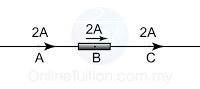
The current flow into a resistor = the current flow inside the resistor = the current flows out from the resistor
IA = IB = IC
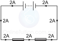
In a series circuit, the current at any points of the circuit is the same.
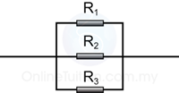
Parallel Circuit
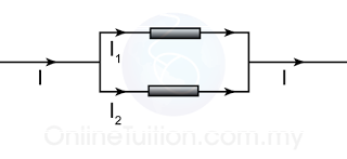
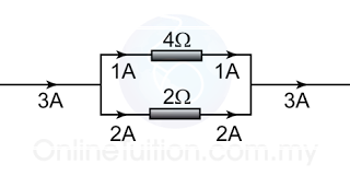
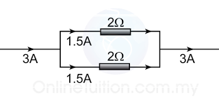
The current flow into a parallel circuit is equal to the sum of the current in each branches of the circuit.
I = I1 + I2
Example
If the resistance of the 2 resistors is the same, current will be divided equally to both of the resistor.
Series Circuit
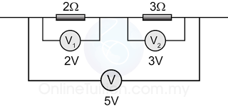
The sum of the potential difference across individual resistor in between 2 points in a series circuit is equal to the potential difference across the two points.
V = V1 + V2
Example
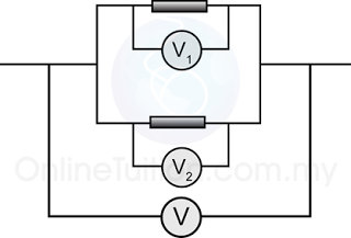
Parallel Circuit
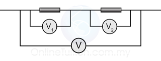
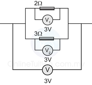
The potential difference across all resistors in a parallel circuit is the same.
V = V1 = V2
Example
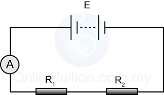
Finding Current in a Series Circuit
- In a series circuit, the current flow through each of the resistor is equal to the current flows through the whole circuit.
- Potential difference (V) across the whole circuit is equal to the e.m.f. (E) if the internal resistance is ignored.
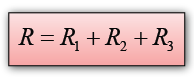
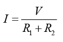
- Effective resistance for the whole circuit = R1 + R2
- By Ohm’s Law
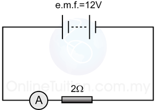
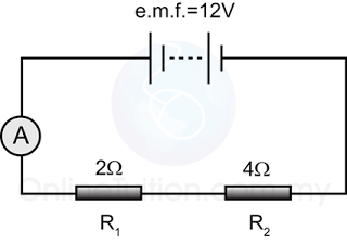
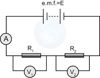
Example 1
For the circuit in the diagram above,
- find the reading of the ammeter.
- find the current flows through the resistor.
Answer:
a.
Potential difference across the 2Ω resistor, V = 12V
Resistance, R =2Ω
V = IR
(12) = I(2)
I = 12/2 = 6A
b.
The current flows through the resistor
= the reading of the ammeter
= 6Ω
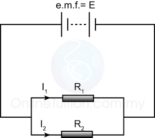
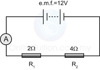
Example 2
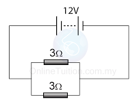
For the circuit above,
- find the reading of the ammeter.
- find the current flows through each of the resistors.
Answer:
a.
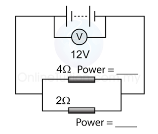
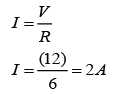
Potential difference across the 2 resistors, V = 12V
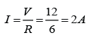
The equivalent resistance of the 2 resistors, R =6Ω
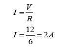
V = IR
(12) = I(6)
I = 12/6 = 2A
b.
The current flows through the resistors
= the reading of the ammeter
= 2Ω
Finding Current in a Parallel Circuit
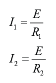
In parallel circuit, the potential difference (V) across each of the resistors is equal to the e.m.f. (E) if the internal resistance of the cell is ignored.
By Ohm’s Law
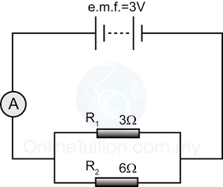
Example 1:
For the diagram above,
a. find the reading of the ammeter.
b. find the current in each of the resistors.
Answer:
a.
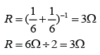
Effective resistance of the 2 resistors in parallel
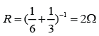
Potential difference across the 2 resistance, V = 3V
V = IR
(3) = I(2)
I = 3/2 = 1.5A
Reading of the ammeter = 1.5A
b.
Current in the 3Ω resistor,
V = IR
(3) = I(3)
I = 3/3 = 1A
Current in the 6Ω resistor,
V = IR
(3) = I(6)
I = 3/6 = 0.5A
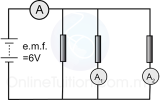
Example 2
Figure above shows 3 identical resistors connected in parallel in a circuit. Given that the resistance of the resistors are 6Ω each. Find the reading of all the ammeters in the figure above.
Answer:
The potential diffrence across the resistors V = 6V
For ammeter A,
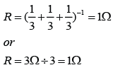
The equivalent resistance = 6/3 = 2Ω.
V = IR
(6) = I(2)
I = 6/2 = 3A
For ammeter A1,
V = IR
(6) = I(6)
I = 6/6 = 1A
For ammeter A2,
V = IR
(6) = I(6)
I = 6/6 = 1A
Finding Potential Difference in a Series Circuit
In the circuit above, if the current in the circuit is I, then the potential difference across each of the resistor is

Example
Find the potential difference across each of the resistors in the diagram above.
Answer:
The potential difference across the 2 resistors, V = 12V
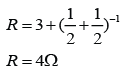
The equivalent resistance of the 2 resistors, R = 2 + 4 = 6Ω
Current pass through the 2 resistor,
For resistor R1,
V = IR
V = (2)(2) = 4V
For resistor R2
V = IR
V = (2)(4) = 8V