5.2.1 Refraction of Light

Refraction is the bending of a light ray at the boundary of two medium as the light ray propagates from a medium to another with difference optical density.
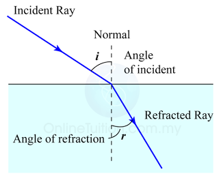
  1. Light rays are bent when they pass at an angle in or out of materials such as glass and water. The effect is called refraction.
  2. Light passing into an optically denser medium is bent towards the normal; light passing into an optically less dense medium is bent away from the normal.
  3. Materials such as glass, water and paraffin are said to be optically denser than air.


5.1.6 Images Formed by Curve Mirror

Finding the Position and Size of the Image

  1. Any two rays are sufficient to fix the position and size of the image. Look for the point where the rays cross after reflection from the mirror.
  2. The interception of the two rays is the focus of the ray.
Example

The Ray Diagram and the Types of Image

The nature and size of the image formed by concave mirrors depends on the distance of the object from the mirror. This will be explained in the following sections.


5.1.4 Reflection of Light by Curved Mirror

Curved Mirror

  1. A curve is part of a circle. Therefore
    1. the centre of the circle will also be the centre of the curve and is called the centre of curvature, and
    2. the radius of the circle will be equal to the radius of the curve, called the curvature radius.

Important Terms


All rays parallel to the principle axis will focus at F


Centre of curvature, C The geometric centre of a hollow sphere of which the concave or convex mirror is a part.
Pole of mirror, P The centre point on the curved mirror.
Principal axis A line which passes through the centre of curvature, C and the pole of a curved mirror, P.
Radius of curvature, r Distance between the pole, P and the centre of curvature, C.
Principal focus, F A point through which all rays travelling parallel to the principal axis converge to or appear to diverge from after reflection by the mirror.
Focal length, f The distance between the principal focus, F and the pole of the
curved mirror, P.
Aperture of mirror The portion of the surface of the mirror that reflects light.
Object distance, u Distance of object from the pole of the mirror, P.
Image distance, v Distance of image from the pole of the mirror,


5.1.3 Constructing Ray Diagram for Plane Mirror

Steps to draw a ray diagram for an image in a plane mirror 

Step 1


( Draw the virtual image. Distance of object = Distance of image )

Step 2


( Draw 2 reflected rays, one from the image to the top of the eye and the other one from the image from the bottom of the eye. )

Step 3

( Draw the respective incident rays for the reflected rays you draw in step 2. )


5.1.2 Images Formed by Plane Mirror

Plane Mirror

Images in plane mirrors

(Reflection of light on a plane mirror)
  1. Figure to the right shows how, by reflecting light, a plane mirror forms an image of a point source of light such as a small light bulb.
  2. The image forms in a mirror is
    1. Upright
    2. Virtual
    3. Laterally inverted
    4. Same size as the object


5.1.1 Reflection of Light


Note: Both the angle of incident and angle of reflection must be measured from the normal.

Laws of Reflection

  1. The law of reflection state that
    1. The angle of incidence is equal to the angle of reflection; the ray leaves the surface at the same angle as it arrives.
    2. The incident ray, the reflected ray and the normal all lie in the same plane; all three could be drawn on the same flat piece of paper

Type of Mirror