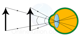
- The angular magnitude of an object is the virtual angle at the eye. It is the angle the object subtends at the eye.
- This angle determines the size of the image (apparent size) formed on the retina and hence governs the apparent size of the object
Positif
|
Negatif
|
|
u
|
Real object
|
Virtual object
|
v
|
Real image
|
Virtual image
|
f
|
Convex lens
|
Concave lens
|
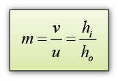
m = linear magnification
u = distance of object
v = distance of image
hi = heigth of image
ho = heigth of object
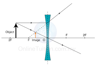
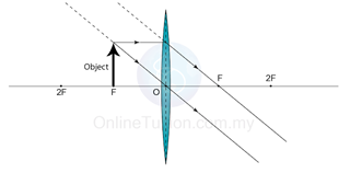
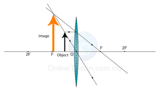
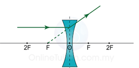
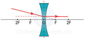
Characteristics of the Image: Virtual, uprigh, magnified
Position of image: at the same side of the object
Lens
|
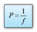
Power of the Lens
|
| Converging (Convex) | Positive |
| Diverging (Concave) | Negative |
| Thick, with short focal length. | High |
| Thin, with long focal length. | Low |
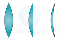
Thinner – Lower Power – Longer Focal Length
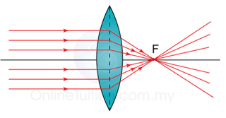
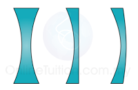
Thicker – Higher Power – Shorter Focal Length
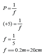
Example:
The power of a lens is labeled as +5D. What is the focal length of the lens (in cm)? Is this a concave lens or a convex lens?
Answer:
| Optical centre, P | Light passing through the central block emerges in the same direction as it arrives because the faces of this block are parallel. P marks the optical centre of the lens. |
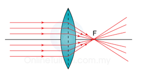
| Principle Axis | The principle axis of a lens is the line joining the centres of of curvature of its surfaces. |
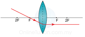
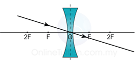
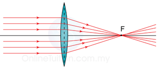
| Principle focus, F | The principle focus of a lens is the point on the priciple axis to which all rays originally parallel and close to the axis converge, or from which they diverge, after passing through the lens. |
| Focal length, f | The focal length of a lens is the distance between the optical centre an the principle focus. |

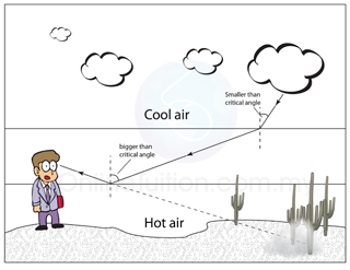
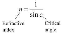
The critical angle can be calculated by using the following equation: