The cathode-ray oscilloscope (C.R.O.) consists of the following components:
- The electron gun.
- The deflecting plates.
- A fluorescent screen.
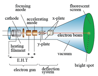
The Electron Gun
| Parts of Electron Gun | Function |
|---|---|
| Filament | To heat the cathode. |
| Cathode | Release electrons when heated by filament. |
| Grid |
|
| Focusing Anode and |
|
| Accelerating anode |
The Deflecting Plates
| Part of the deflecting system | Function |
|---|---|
| Y-plate | The Y-plates will cause deflection in the vertical direction when a voltage is applied across them. |
| X-plate | On the other hand, the X-plates will cause the electron beam to be deflected in the horizontal direction if a voltage is applied across them. |
The Fluorescent Screen
- The screen is coated with a fluorescent salt, for example, zinc sulphide.
- When the electrons hit the screen, it will cause the salt to produce a flash of light and hence a bright spot on the screen.
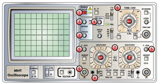
Using CRO
| Function | |
|---|---|
| 1. Power switch | To switch on and off of the oscilloscope |
| 2. Focus control | To control the focus of the spot on the screen. |
| 3. Intensity control | To control the brightness of the spot on the screen. |
| 4. X-offset 5. Y-offset |
Y-offset moves the whole trace vertically up and down on the screen, while X-offset moves the whole trace from side to side on the screen. |
| 6. Time base control | Whenever we switch on the time-base, we are actually applying a sawtooth voltage to the X-plates (Figure below). * This make the electron beam sweep across the screen at a constant speed. * By knowing the period of each cycle, T, we can then know how fast the beam is sweeping across the screen. The time-base is thus a measure of time for the oscilloscope. |
| 7. Y gain control | * the "Volts/Div." wheels amplify an input signal so that for a division a given voltage level is in valid. A "division" is a segment, a square on the screen of the oscilloscope. * A setting of ".5" i.e. means, that the height of a single square equals a voltage of 0.5 V. An amplitude of 1 V would have a size of two divisions vertical to the abscissa. |
| 8. d.c./a.c. switch | d.c. – d.c. and a.c. voltage displayed. a.c. – only a.c. voltage displayed. |
| 9. X-input and Y-input | Electric input connect to the X-plate and Y-plate. |
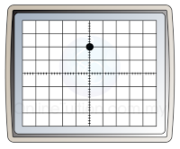
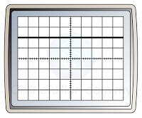
Example
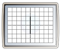
Table below shows the sample display of direct current and alternating current when the time base is switched ON and OFF.
 |
 |
|---|---|
| Direct Current (Time Base Switched Off) | Direct Current (Time Base Switched On) |
 |
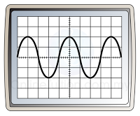 |
| Alternating Current (Time Base Switched Off) | Alternating Current (Time Base Switched On) |