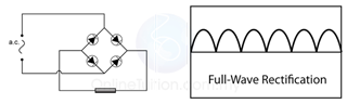
Figure above shows a circuit to produce full-wave rectification.
Using an ingenious arrangement of diodes, called a bridge rectifier, this reverses the negative half of each a.c. cycle, instead of just blocking it.
The result is that current always flows in the same direction through the load, no matter which way it leaves the supply.
Combine a transformer (to reduce mains voltage) with a bridge rectifier and a smoothing capacitor, and you have a mains-operated d.c. power supply - as used in radios, instead of batteries.
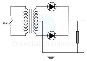
Another method of full wave rectification is arrange two diode to the output of a transformer as show below. A similar result will be produced.
Smoothing
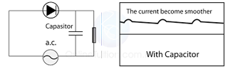
In the circuit above, the `one-way' direct current flows in a series of surges with brief periods of zero current in between.
These surges can be partly smoothed out by connecting a large capacitor across the load.
The capacitor charges up when current flows from the diode, then discharges through the load when the current from the diode is zero.
Smoothed in this way, the current through the load is similar to the steady direct current which would flow from a battery.