- A transistor is a double p-n junction semiconductor with three terminals,
- the emitter (e),
- the base (b)
- the collector (c).
- Figure below shows the illustration of a transistor. It looks like a combination of 2 p-n junction diodes.
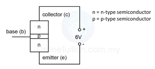
- In a transistor, the emitter emits charge carriers (free electrons or holes).
- The charge carriers move towards the base.
- Under certain condition, large amount of the charge carriers will pass through the thin base layer and to be collected by the collector.
Types of the Transistors
- There are 2 types of transistors:
- npn transistor
- pnp transistor
- Figure 2 below shows the illustration of the npn and pnp transistor and Figure 3 below shows the symbol of both npn and pnp transistor.
- For the symbol of the transistor, the arrow shows the direction of current. Take note that, for the emitter and base, the current always flow from the positive terminal to the negative terminal.
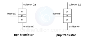 |
| (Figure 2: Illustration of the npn and pnp transistor) |
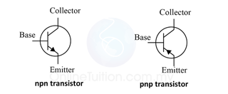 |
| (Figure 3: Symbol of the npn and pnp transistor) |
How a Transistor Work?
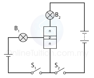 |
| (Figure 4) |
- In the Figure 4 above, there are 2 circuits in the connection:
- the base circuit
- the collector circuit
- The base circuit is forward bias whereas the collector circuit is reverse bias (This will be discuss in "The Connection of a Transistor").
- Table below shows the response of bulb 1 (B1) and bulb 2 (B2) when switch 1 (S1) and switch 2 (S2) are closed.
S1
|
S2
|
B1
|
B2
|
Open
|
Open
|
Does not light up
|
Does not light up
|
Close
|
Open
|
Light up
|
Does not light up
|
Open
|
Close
|
Does not light up
|
Does not light up
|
Close
|
Close
|
Light up
|
Light up
|
- From the table, we can see that, the collector circuit is controlled by the base circuit.
- Current will flow in collector circuit only when the base circuit is closed.
Connection of Transistor
- The terminals of a transistor must be connected to the terminals of a cell correctly to avoid damaging the transistor.
- Transistor should be connected in such a way that
- the emitter-base circuit is forward bias
- the collector-base circuit is reverse bias.
Example:
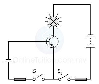
Emitter-Base: Forward Bias
Collector-Base: Reverse Bias
Connection: CORRECT

Emitter-Base: Forward Bias
Collector-Base: Reverse Bias
Connection: CORRECT
Example:
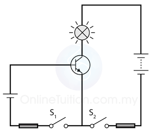
Emitter-Base: Forward Bias
Collector-Base: Reverse Bias
Connection: CORRECT

Emitter-Base: Forward Bias
Collector-Base: Reverse Bias
Connection: CORRECT
Example:
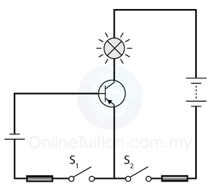
Emitter-Base: Forward Bias
Collector-Base: Forward Bias
Connection: INCORRECT

Emitter-Base: Forward Bias
Collector-Base: Forward Bias
Connection: INCORRECT
Example:
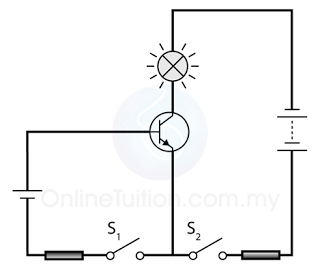
Emitter-Base: Forward Bias
Collector-Base: Forward Bias
Connection: INCORRECT

Emitter-Base: Forward Bias
Collector-Base: Forward Bias
Connection: INCORRECT
Current in a Transistor
- The current flows in the base, emitter and collector is called the base current (IB), the emitter current(IE) and the collector current(IC) respectively.
- Figure below shows the direction of the current in an npn transistor.
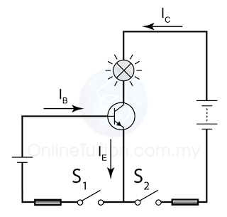
- In general, IE is related to IB and IC through the formula
IE = IB + IC
Another thing that you need to know about the 3 currents is
IE > IC > IB