8.3.3 Induced Current in a Solenoid

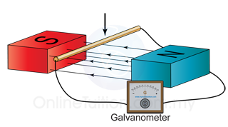
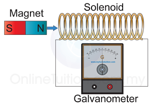
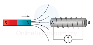
  1. When a bar magnet is inserted into a solenoid, the solenoid will cut the magnetic flux of the bar magnet. This will induce a current and emf in the solenoid.
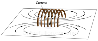
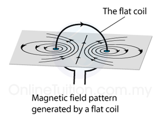
  2. The induced current will produce another magnetic field around it.
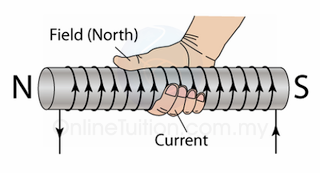
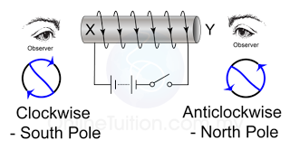
  3. The pole of the magnetic field and direction of the induced current can be determined by using Lenz's Law as explained in the video below.


8.3.2 Induced Current in a Straight Wire

  1. When a straight conductor (or wire) moves and cut a magnetic field, emf will be induced across the conductor.
  2. If the conductor is in a complete circuit, current will flow in the conductor.
  3. The direction of the current induced can be determined by using Fleming's Right Hand Rule, as explained in the video below.


8.3.1 Electromagnetic Induction

  1. When a magnet is moved into and out of the solenoid, magnetic flux is being cut by the coil. 
  2. The cutting of magnetic flux by the wire coil induces an e.m.f in the wire. 
  3. When the solenoid is connected to a closed circuit, the induced current will flow through the circuit.
  4. The production of electric current by changing magnetic field is called electromagnetic induction.
  5. Current/emf is induced only when there is relative motion between the magnetic field and the conductor.
  6. The direction of the induced current and the magnitude of the induced e.m.f due to the cutting of the magnetic flux can be determined from Lenz's Law and Faraday's Law.

Lenz's Law

  1. When a magnet is moved into and out of a coil, the induced current that flows through the coil can be determined from Lenz's Law.
  2. Lenz's Law states that the induced current always flows in the direction that opposes the change in magnetic flux.
  3. Lenz's Law obeys the principle of conservation of energy. Work is done to move the magnet against the repulsive force. This work done is converted to electric energy which manifests as an induced current.
  4. For a conductor in a closed circuit moving perpendicular to a magnetic field and hence cutting its magnetic flux, the direction of the induced current is determined from Fleming's Right-Hand Rule.
  5. Fleming's Right-Hand Rule is used to determine the direction of the induced current that flows from the wire when there is relative motion with respect to the magnetic field


8.2.3 Direct Current Motor

  1. An electric motor converts electrical energy to kinetic energy.
  2. Diagram above shows the structure of a simple direct current motor (DC motor).
  3. It consist a rectangular coil of wire placed between 2 permanent magnets.
  4. The coil are soldered to a copper split ring known as commutator. 2 carbon brushes are held against the commutator.
  5. The function of the brush is to conduct electricity from the external circuit to the coil and allow the commutator to rotate continuously.
  6. The function of the commutator is to change the direction of the current in the coil and hence change the direction of the couple (the 2 forces in opposite direction) in every half revolution. This is to make sure that the coil can rotate continuously.
  7. The operation principle of a direct current motor are explained in detail in the second Youtube video below.


8.2.2 Turning Effect of a Current Carrying Coil in a Magnetic Field

  1. If a current carrying coil is placed in a magnetic field (As shown in diagram above), a pair of forces will be produced on the coil. This is due to the interaction of the magnetic field of the permanent magnet and the magnetic filed of the current carrying coil.
  2. The diagram below shows the catapult field produced.
  1. The direction of the force can be determined by Fleming's left hand rule.
  2. Since the current in both sides of the coil flow in opposite direction, the forces produced are also in opposite direction. The 2 forces in opposite direction constitute a couple which produces a turning effect to make the coil rotate.
  3. Examples of electric equipment whose operation is based on this turning effect are
    1. the direct current motor
    2. the moving coil meter.

Moving Coil Meter


Light Indicator

A light indicator which has lower inertia  is used to increase the sensitivity of the meter.

Linear Scale

  1. Due to the radial magnetic field and the cylindrical soft-iron core, a linear scale is produced.
  2. A linear scale is more accurate and easier to be read.

Mirror

  1. A mirror is used to prevent parallax error.
  2. When the observer's eye is exactly above the indicator, the indicator will cover its own image on the mirror. 
  3. This can used to prevent parallax error.

Curved Permanent Magnet

  1. A curved permanent magnet is used to produce a radial field.
  2. A radial field is a magnetic field where the field lines are either pointing away or toward the center of the field.
  3. A radial can be focused by a cylindrical soft-iron core.

Rectangular Coils

  1. When a current flows through the coils, a force will be generated due to the interaction between the magnetic field of the permanent magnet and the coil.
  2. The force will turn the coils, which in turn move the indicator.

Cylindrical Soft-Iron Core

  1. A cylindrical soft iron core is placed inside the radial field produced by the curved magnet.
  2. A soft-iron core can focus the magnetic field of the permanent magnet.

Hair Spring

  1. The deflection of the coil and the indicator stops when the force is balanced by the opposing force from the hair spring.
  2. The angle of deflection is directly proportional to the magnitude of the current in the coil.

Loud Speaker

  1. The loud speaker contains a cylindrical coil which is free to move in a radial magnetic field set up by a strong cylindrical permanent magnet.
  2. The magnet has a central South Pole and a surrounding North Pole. The field lines are therefore radial and at right angles to the turns of the-coil.
  3. When varying the current flows through the coil, a force of varying magnitudes will act on the coil. This will cause the coil to move to and fro according to the magnitude of the force.
  4. The paper cone then vibrates to produce sound waves.


8.2.1 Force on a Current Carrying Conductor in a Magnetic Field

  1. We have learned that when current flows in a conductor, a magnetic field will be generated.
  2. When the current-carrying conductor is placed in a magnetic field, the interaction between the two magnetic fields will produce a resultant field known as the catapult field as shown in the figure below.
  3. The catapult field is a non-uniform field where the field at one side is stronger than the other side.
  4. As a result, a force is produced to move the current carrying conductor from the stronger field to the weaker field.
  5. The force produced by a catapult field is called the catapult force.
  6. The direction of the force can be determined by Fleming's left hand rule as shown in Figure below.
  7. The fore finger, middle finger and the thumb are perpendicularly to each other. The forefinger points along the direction of the magnetic field, middle finger points in the current direction and the thumb points along the direction of the force.
  8. The strength of the force can be increased by:
    1. Increase the current
    2. Using a stronger magnet
    3. using a longer wire
    4. arranging the wire perpendicular to the direction of the magnetic field.

Force between 2 Current-Carrying Conductors

  1. When 2 current carrying conductors are placed close to each other, a force will be generated between them.
  2. If the current in both conductors flow in the same direction, they will attract each other, whereas if the current are in opposite direction, they will repel each other.
  3. This force is due to the interaction between the magnetic field of the 2 conductor.
  4. The figure below shows the catapult field produced by 2 current carrying conductors when their current is in the same direction or opposite direction.

(Magnetic field generated when 2 current carrying conductors with currents move in the same direction are brought close to each other. The field will cause the 2 conductors attract each other)
(Magnetic field generated when 2 current carrying conductors with currents move in the opposite direction are brought close to each other. The field will cause the 2 conductors repel each other)

Summary:
  1. A force will be produced between 2 current carrying conductors.
  2. If the currents are in the same direction, the 2 wire will attract each other.
  3. If the current are in opposite direction, the 2 wire will repel each other.


8.1.5 Applications of Electromagnet

Door Bell

  1. When the switch is on, the circuit is completed and current flows.
  2. The electromagnet becomes magnetised and hence attracts the soft-iron armature and at the same time pull the hammer to strike the gong. This enables the hammer to strike the gong.
  3. As soon as the hammer moves towards the gong, the circuit is broken. The current stops flowing and the electromagnet loses its magnetism. This causes the spring to pull back the armature and reconnect the circuit again.
  4. When the circuit is connected, the electromagnet regain its magnetism and pull the armature and hence the hammer to strike the gong again.
  5. This cycle repeats and the bell rings continuously.

Electromagnetic Relay

  1. A relay is an electrical switch that opens and closes under the control of another electrical circuit.
  2. The switch is operated by an electromagnet to open or close one or many sets of contacts.
  3. A relay has at least two circuits. One circuit can be used to control another circuit. The 1st circuit (input circuit) supplies current to the electromagnet.
  4. When the switch is close, the electromagnet is magnetised and attracts one end of the iron armature.
  5. The armature is then closes the contacts (2nd switch) and allows current flows in the second circuit.
  6. When the 1st switch is open again, the current to the electromagnet is cut, the electromagnet loses its magnetism and the 2nd switch is opened. Thus current stop to flow in the 2nd circuit.

Circuit Breaker


  1. Figure above shows the structure of a circuit breaker.
  2. A circuit breaker is an automatic switch that cut off current in a circuit when the current become too large.
  3. When the current in a circuit increases, the strength of the electromagnet will increase in accordance; this will pull the soft iron armature towards the electromagnet.
  4. As a result, the spring pulls apart the contact and disconnects the circuit immediately, and the current stop to flow.
  5. We can reconnect the circuit by using the reset button. The reset button can be pushed to bring the contact back to its original position to reconnect the circuit.

Telephone Earpiece

  1. An electromagnet is used in the earpiece of a telephone. The figure shows the simple structure of a telephone earpiece.
  2. When you speak to a friend through the telephone, your sound will be converted into electric current by the mouthpiece of the telephone.
  3. The current produced is a varying current and the frequency of the current will be the same as the frequency of your sound.
  4. The current will be sent to the earpiece of the telephone of your friend.
  5. When the current passes through the solenoid, the iron core is magnetised. The strength of the magnetic field changes according to the varying current.
  6. When the current is high, the magnetic field will become stronger and when the current is low, the magnetic field become weaker.
  7. The soft-iron diaphragm is pulled by the electromagnet and vibrates at the frequency of the varying current. The air around the diaphragm is stretched and compressed and produces sound wave.
  8. The frequency of the sound produced in the telephone earpiece will be the same as your sound.


8.1.4 Solenoid

A solenoid is a long coil made up of a numbers of turns of wire.

Magnetic Field Pattern

  1. Figure (a) illustrates the field pattern produced by a solenoid when current pass through it.
  2. The field lines in the solenoid are close to each other, indicates that the magnetic field is stronger inside the solenoid.
  3. We can also see that the field lines are parallel inside the solenoid. This shows that the strength of the magnetic filed is about uniform inside the solenoid.
  4. We can also see that the magnetic field of a solenoid resembles that of the long bar magnet, and it behaves as if it has a North Pole at one end and a South Pole at the other.

(Figure (a): Magnetic field pattern of a solenoid)

Determining the Pole of the Magnetic Field

  1. The pole of the magnetic field of a solenoid can be determined by the Right Hand Grip Rule.
  2. Imagine your right-hand gripping the coil of the solenoid such that your fingers point the same way as the current. Your thumb then points in the direction of the field.
  3. Since the magnetic field lines always come out from the North Pole, hence the thumb points towards the North Pole.

[Figure (b)]
  1. There is another method can be used to determine the poles of the magnetic field forms by a solenoid.
  2. Try to visualise that you are viewing the solenoid from the 2 ends as illustrated in figure (c) below.
  3. The end will be a North pole if the current is flowing in the aNticlockwise, or a South pole if the current is flowing in the clockwiSe direction.

Strength of the Magnetic Field

The strength of the magnetic field can be increased by
  1. increasing the current,
  2. increasing the number of turns per unit length of the solenoid,
  3. using a soft-iron core within the solenoid.


8.1.3 Current in a Coil

Field Pattern

  1. Figure (a) below shows the field pattern produced by a current flowing in a circular coil.
  2. In SPM, you need to know the field pattern, the direction of the field and the factors affect the strength of the field.
  3. The direction of the field can be determined by the Right Hand Grip Rule. Grip the wire at one side of the coil with your right hand, with thumb pointing along the direction of the current. Your other fingers will be pointing in the direction of the field.
Figure (a)
  1. Figure (b) shows the plan view of the field pattern.

Factors Affecting the Strength

There are 3 ways to increase the strength of the magnetic field:
  1. increase the current and
  2. increase the number of turns of the coil.
  3. use coil with smaller radius


8.1.2 Current in a Straight Wire

Magnetic Field Pattern

(Figure (a))
  1. The magnetic field generated by a straight wire are concentric circles around the wire as shown in figure (a) above.
  2. Take notes that when the direction of the current is reversed, the direction of the magnetic field line is also reversed.
  3. The direction of the magnetic field line can be determined by the Maxwell's Screw Rule or the Right Hand Grip Rule.

(Figure (b): The plan view of the magnetic field generated by a straight wire)
  1. Sometime, the magnetic field pattern may be given in plan view, as shown in figure (b).
  2. In plan view, a dot in the wire shows the current coming out from the plane whereas a cross in the wire shows the current moving into the plane.
(Figure (c): A dot indicates the current move out from a plane whereas a cross indicates the current move into the plane)

Direction of the Magnetic Field

The direction of the magnetic field formed by a current carrying straight wire can be determined by the
  1. Right Hand Grip Rule or the 
  2. Maxwell Screw Rule.

Right Hand Grip Rule

Grip the wire with the right hand, with the thumb pointing along the direction of the current. The other fingers give the direction of the magnetic field around the wire. This is illustrated in the figure below.
(Figure (d))

The Maxwell's Screw Rules
The Maxwell Screw Rules sometime is also called the Maxwell's Corkscrew Rule. Imagine a right handed screw being turn so that it bores its way in the direction of the current in the wire. The direction of rotation gives the direction of the magnetic field.

(Figure (e))


Strength of the Magnetic Field

  1. The strength of the magnetic field form by a current carrying conductor depends on the magnitude of the current.
  2. A stronger current will produce a stronger magnetic field around the wire as shown in Figure (f) below.
    (Figure (f))
  3. The strength of the field decreases out as you move further out. This is illustrated in figure (g) below. Thus, you must be very careful when you are asked to draw the magnetic field in your exam.
    (Figure (g)
  4. The distance of the field lines must increase as it is further out form the wire.